
Bluetooth Control Home Automation Using Esp 32 (BLE)

 Bluetooth Control Home Automation Using Esp 32 (BLE)


Hello, Friends Welcome to my Channel "Electrify Circuit". This video is Bluetooth Control Home Automation Using Esp 32 (BLE). Control Home Appliances Using Andriod Phone App it's very used for a handicapped person.


  For the last few years, the wireless world has been bombarded daily with information about a new generation of radio frequency(RF) technologies that would profoundly impact. if not revolutionize.the way we bye and contact our businesses.


‘The wireless-networking standard technology called Bluetooth has quietly become a common way to replace the wires on short distances. With a gadget such as a smartphone (Android Phone) or a tablet featured with a Bluetooth module, a wireless connection is the easiest way to send and receive information, And because this technology spread in the prototyping circuit, it’s often used to control things wirelessly.


This project work explains how to control electrical appliances using an Android device. Operating conventional wall switches is difficult for physically handicapped or elder people. This project provides the solution to this problem by integrating all the electrical appliances into a control unit that can be operated by an Android application device (Android smartphone or Tablet). The proposed system controls the electrical loads based on the data transmitted by the Android device. An android application should be installed in the user's mobile or tablet to control the electrical loads, Using this android application user can send the commands to the Bluetooth module to control the electrical loads. The wireless technology used in this project is Bluetooth It can also be called an “Android-based Home AutomationSystem” or “Remote Password Operated Electronic Home Appliances Control System”.

Mager Components


Esp 32 (BLE):-   ESP32 has a lot more features than ESP8266 and it is difficult to include all the specifications in this Getting Started with ESP32 guide. So, I made a list of some of the important specifications of ESP32 here. But for a complete set of specifications, I strongly suggest you refer to the Datasheet.

Specifications:-

  • Single or Dual-Core 32-bit LX6 Microprocessor with clock frequency up to 240 MHz.
  • 520 KB of SRAM, 448 KB of ROM, and 16 KB of RTC SRAM.
  • Supports 802.11 b/g/n Wi-Fi connectivity with speeds up to 150 Mbps.
  • Support for both Classic Bluetooth v4.2 and BLE specifications.
  • 34 Programmable GPIOs.
  • Up to 18 channels of 12-bit SAR ADC and 2 channels of 8-bit DAC
  • Serial Connectivity include 4 x SPI, 2 x I2C, 2 x I2S, 3 x UART.
  • Ethernet MAC for physical LAN Communication (requires external PHY).
  • 1 Host controller for SD/SDIO/MMC and 1 Slave controller for SDIO/SPI.
  • Motor PWM and up to 16-channels of LED PWM.
  • Secure Boot and Flash Encryption.


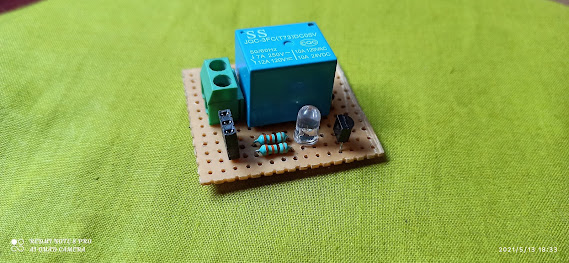
Relay:- Relays are the most commonly used switching device in electronics. Let us learn how to use one in our circuits based on the requirement of our project.

Features of 5-Pin 5Volt Relay

  • Trigger Voltage (Voltage across coil) : 5V DC
  • Trigger Current (Nominal current) : 70mA
  • Maximum AC load current: 10A @ 250/125V AC
  • Maximum DC load current: 10A @ 30/28V DC
  • Compact 5-pin configuration with plastic moulding
  • Operating time: 10msec Release time: 5msec
  • Maximum switching: 300 operating/minute (mechanically)


Relay Pin Configuration

Coil 1:-  Used to trigger(On/Off) the Relay, Normally one end is connected to 5V and the other end to the ground.
Coil  2:-  Used to trigger(On/Off) the Relay, Normally one end is connected to 5V and the other end to the ground.
Common (COM):- Common is connected to one End of the Load that is to be controlled.
Normally Closed (NC):- The other end of the load is either connected to NO or NC. If connected to NC the load remains connected before the trigger.
Normally Open (NO):- The other end of the load is either connected to NO or NC. If connected to NO the load remains disconnected before the trigger.

Required Components:-

- Esp 32 (BLE) - Breadboard - 5v Relay Module - Jumper wire - Bulb Holder - 1.00 sqmm Wire


Tutorial Video:


Circuit Diagram Relay Module:


Code, Circuit Diagram Download Link:-


How to Test Esp32 Bluetooth Led On/Off To App:- https://youtu.be/AiQ5IF_j--k How To Make a 5V Relay Module At Home and Check using Arduino:- https://youtu.be/ZMewjmbJu4c How to Decode IR Remote Value Using Arduino UNO:- https://youtu.be/TXoin8xyX6Y LED shifting using push-button and Arduino nano:-https://youtu.be/9uNiHqaziqs 7-segment 0-9 counter using Arduino Nano:-https://youtu.be/hTY3PsQ7H9A How to test Arduino Nano | How to led blink with Arduino nano:-https://youtu.be/Rbdl2Ii10b0 How to make full bridge rectifier | 0 to 12v voltage regulator | Rectifier + voltage regulator:-https://youtu.be/hkHfuVJYLr4

Comments

Popular posts from this blog

How To Control 12v RGB Led Strip Using Arduino And BC 547 Transistor With Code

  How To Control 12v RGB Led Strip Using Arduino And BC 547 Transistor With Code Hello, Friends Welcome to my channel Electrify Circuit Today Video How To Control RGB Led Strip Using Arduino And BC 547 Transistor. View full video. Required Components:- -Arduino NANO -Breadboard -RGB Led Strip -Jumper wire - BC 547 Transistor Circuit Diagram:- Video:- Code, Circuit Diagram Download Link:- Click Here Others Videos:- How to Test Esp32 Bluetooth Led On/Off To App:- https://youtu.be/AiQ5IF_j--k How To Make a 5V Relay Module At Home and Check using Arduino:- https://youtu.be/ZMewjmbJu4c How to Decode IR Remote Value Using Arduino UNO:- https://youtu.be/TXoin8xyX6Y LED shifting using push-button and Arduino nano:- https://youtu.be/9uNiHqaziqs 7-segment 0-9 counter using Arduino Nano:- https://youtu.be/hTY3PsQ7H9A How to test Arduino Nano | How to led blink with Arduino nano:- https://youtu.be/Rbdl2Ii10b0 How to make full bridge rectifier | 0 to 12v voltage regulator | Rec

HowTo Make Variable Power Supply Using LM317

  How to make variable power supply using lm317 | #newvideo2021 #newvideo #voltageregulator #variablepowersupply #diy #lm317 #bd139 #tip3055 This Project is to make a simple variable Power supply in LOW cost. Mager Components LM317-: The LM317 is an adjustable 3-terminal positive voltage regulator capable of supplying different DC voltage outputs other than the fixed voltage power supply of +5 or +12 volts or as a variable output voltage from a few volts up to some maximum value all with currents of about 1.5 a mperes. BD139 Transistor:- BD139 is an NPN transistor hence the collector and emitter will be left open (Reverse biased) when the base pin is held at the ground and will be closed (Forward biased) when a signal is provided to the base pin BD139 has a gain value of 40 to 160, this value determines the amplification capacity of the transistor. The maximum amount of current that could flow through the Collector pin is 1.5A, hence we cannot connect loads that consume more

How to Test Esp32 Bluetooth Led On/Off To App

How to Test Esp32 Bluetooth Led On/Off To App   #arduino #esp32 #arduinoproject # NodeMCU Hello, Friends Welcome to my channel ElectriCircuit Today Video is How to test Esp32 Bluetooth using App make an app using MIT App inventor. One led On/off Using Android App. Required Components:- -ESP 32 Board -Breadboard -LED -Resistor -Jumper wire Code, App, Circuit Diagram, aia file Download Link:- Click Here