How to make variable power supply using lm317 |
#newvideo2021 #newvideo #voltageregulator #variablepowersupply #diy #lm317 #bd139 #tip3055
This Project is to make a simple variable Power supply in LOW cost.

Mager Components
LM317-:
The LM317 is an adjustable 3-terminal positive voltage regulator capable of supplying different DC voltage outputs other than the fixed voltage power supply of +5 or +12 volts or as a variable output voltage from a few volts up to some maximum value all with currents of about 1.5 amperes.

BD139 Transistor:-
BD139 is an NPN transistor hence the collector and emitter will be left open (Reverse biased) when the base pin is held at the ground and will be closed (Forward biased) when a signal is provided to the base pin
BD139 has a gain value of 40 to 160, this value determines the amplification capacity of the transistor. The maximum amount of current that could flow through the Collector pin is 1.5A, hence we cannot connect loads that consume more than 1.5A using this transistor. To bias a transistor we have to supply current to the base pin, this current (IB) should be limited to 1/10th of the collector current, and the voltage across the base-emitter pin should be 5V maximum. age.
PINOUT:-
Emitter:- Current Drains out through emitter, normally connected to ground
Collector:- Current flows in through collector, normally connected to load
Base:- Controls the biasing of the transistor, Used to turn ON or OFF the transistor.
Features:-
Plastic casing NPN Transistor
Continuous Collector current (IC) is 1.5A
Collector-Emitter voltage (VCE) is 80 V
Collector-Base voltage (VCB) is 80V
Base Current (Ib) is 0.5A
Emitter Base Breakdown Voltage (VBE) is 5V
DC current gain (hFE) is 40 to 160

More Details: Complete Technical Details can be found at the BD139 transistor datasheet
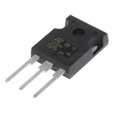
TIP3055:-
TIP3055 is a three-layer NPN device within the working range, the collector current IC is a function of the base current IB, a change in the base current giving a corresponding amplified change in the collector current for a given collector-emitter voltage VCE.
Features:-
Low saturation voltage
Simple drive requirements
The high safe operating area
For low distortion complementary designs
Easy to carry and handle
Transistor Polarity NPN
Collector−Emitter Voltage (VCEO) 60V
Collector−Base Voltage (VCBO) 7V
Continuous Collector Current (Ic) 15A
Continuous Base Current (Ib) 7A
Emitter Base Voltage (VEBO) 1.8V
Power Dissipation (Pd) 90W
Operating Temperature Range -65 - 150°C
DC Current Gain (hFE) 20-70
More Details: Complete Technical Details can be found at the TIP3055 transistor datasheet
Tutorial Video:-
2× 2 pin PCB mount terminal block
Circuit Diagram:-

Schematic:-

Code, Circuit Diagram Download Link:-
https://drive.google.com/drive/folders/1O_60CSdK2t1oYi2F-39S0bn6ajjwTior?usp=sharing
How to Test Esp32 Bluetooth Led On/Off To App:-
https://youtu.be/AiQ5IF_j--k
How To Make a 5V Relay Module At Home and Check using Arduino:-
https://youtu.be/ZMewjmbJu4c
How to Decode IR Remote Value Using Arduino UNO:-
https://youtu.be/TXoin8xyX6Y
LED shifting using push-button and Arduino nano:-https://youtu.be/9uNiHqaziqs
7-segment 0-9 counter using Arduino Nano:-https://youtu.be/hTY3PsQ7H9A
How to test Arduino Nano | How to led blink with Arduino nano:-https://youtu.be/Rbdl2Ii10b0
How to make full bridge rectifier | 0 to 12v voltage regulator | Rectifier + voltage regulator:-https://youtu.be/hkHfuVJYLr4
Comments
Post a Comment